
Views: 0 Author: Site Editor Publish Time: 2026-09-19 Origin: Site


Optical detection dictates the reliability of modern hardware design. Engineers often treat these components as simple circuit additions, but specification errors carry heavy penalties. Selecting the wrong proximity detection component leads to immediate system failures. You will face false triggers on the assembly line or environmental interference from direct sunlight in the field. These issues force hardware revisions late in the product development cycle, delaying launches and burning engineering hours.
This technical teardown examines optical detection mechanics from the ground up. We will break down how an infrared proximity sensor functions across volatile real-world environments. Product managers and hardware engineers need precise, field-tested evaluation criteria to specify the right component for their exact application environment. Understanding these core principles prevents catastrophic field failures, ensures reliable operation, and keeps your project timeline intact.
Component Architecture: An infrared proximity sensor relies on a paired IR transmitting LED and a receiving photodiode to calculate distance or presence based on light reflection or time-of-flight.
Environmental Vulnerabilities: Ambient light, surface color, and material reflectivity heavily influence accuracy, requiring specific mitigation strategies like signal modulation.
Technology Trade-offs: While highly cost-effective and fast, standard IR sensors struggle with dark or transparent objects, necessitating a careful comparison against ultrasonic or capacitive alternatives.
Specification Focus: Successful integration requires evaluating datasheets not just for maximum range, but for beam angle, power consumption, and thermal stability under real-world conditions.
The transmitting LED pushes light in the 700nm to 1mm wavelength range. We typically use 850nm or 940nm for industrial applications. This spectrum remains completely invisible to the human eye, preventing distraction in user-facing devices. The receiving component detects this specific wavelength. Engineers rely on a photodiode or phototransistor for this task. The receiver generates a small current when exposed to the correct light frequency, acting as the system's eyes.
Physical alignment between the emitter and receiver dictates performance. Optical isolation prevents internal cross-talk. Without proper mechanical baffling, light leaks directly from the emitter into the receiver inside the housing. This leakage causes permanent false positive readings. You must ensure an opaque barrier, usually black ABS plastic or specialized epoxy, separates the two elements on the PCB. We often design custom light pipes to guide the beam exactly where it needs to go.
Active IR systems emit light to measure reflection or proximity. They require continuous power to drive the transmitting LED forward current. Passive IR (PIR) systems do not emit any light. They only measure ambient thermal radiation and body heat changes across a segmented lens. Both technologies serve entirely different engineering purposes on the factory floor.
PIR handles wide-area motion detection. You will find PIR in security systems, warehouse lighting, and HVAC occupancy controls. Active infrared proximity sensors handle precise distance measurement. They detect presence within a defined, narrow field of view. Choose active sensors for robotics, touchless interfaces, and conveyor belt part counting.
| Feature | Active Infrared | Passive Infrared (PIR) |
Emission | Emits IR light (850nm/940nm) | None (Receives only) |
Primary Target | Physical objects (any temperature) | Thermal signatures (body heat) |
Field of View | Narrow, directional beam | Wide, segmented area |
Power Draw | Higher (drives LED) | Very Low (passive listening) |
The basic reflection mechanism operates on simple physics. IR light leaves the emitter and strikes a target object. The surface reflects a portion of this light back to the receiver. Analog sensors use the angle of the reflected light to estimate distance. We call this method triangulation. Triangulation provides highly accurate distance measurements regardless of surface color, as it relies on geometry rather than raw light intensity.
Other analog sensors measure the intensity of the returned signal. Closer objects reflect more light, generating a stronger voltage spike. Digital proximity sensors use threshold logic. They trigger a binary output when the signal crosses a specific voltage level set by a comparator. This provides a simple presence or absence indication for basic logic controllers.
Internal circuitry manages the raw, noisy sensor data. Operational amplifiers (op-amps) boost the weak photodiode signal. This amplification makes the signal usable for downstream processing. Comparators convert analog voltage variations into clean digital signals. They output a clear High or Low state, often using an open-collector output that requires a pull-up resistor on your main board.
Microcontroller integration requires careful pin mapping and code architecture. Distance-resolved sensors connect to ADC (Analog-to-Digital Converter) pins. Threshold-based digital outputs connect to GPIO (General Purpose Input/Output) pins. You must configure hardware interrupt handling for fast response times. Industrial-grade sensors include built-in signal conditioning. They feature RC noise filtering mechanisms to reject electrical interference from nearby motors and relays.
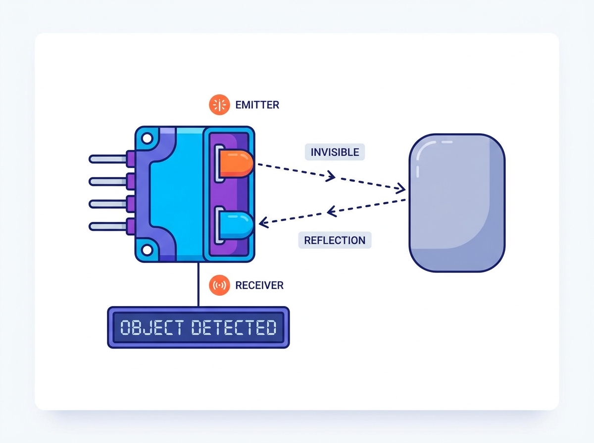
Standard reflective sensors feature a unified transceiver package. The emitter and receiver sit side-by-side in the same plastic housing. They face the same direction to detect reflected light from a target. This compact design simplifies mechanical integration and reduces PCB footprint.
These sensors excel in short-range object detection. Engineers use them for edge detection in automated guided vehicles (AGVs). They also serve well in basic presence sensing applications. Paper detection in commercial printers relies heavily on this standard package to monitor the paper path and detect jams.
Break beam sensors use an opposed-mode setup. The emitter and receiver face each other across a physical gap. The receiver constantly sees the emitted light. An object passing between them breaks the beam, dropping the receiver voltage and triggering the sensor.
This method offers unmatched reliability. It ignores surface color, ambient light, and reflectivity entirely. Engineers specify transmissive sensors for high-speed counting applications. They form the basis of safety light curtains on stamping presses. You should use them in harsh environments where reflection is unpredictable or targets are highly variable.
Time-of-Flight (ToF) technology represents a massive leap in optical detection. A ToF infrared sensor measures the actual time light takes to leave the emitter, hit the target, and return. It does not rely on the intensity of the reflected light. The sensor emits a short, high-power pulse and times the echo using a highly accurate internal clock.
ToF sensors provide immunity to surface color variations. A matte black object reads at the exact same distance as a glossy white object. They offer significantly higher distance accuracy over longer ranges. Use ToF when precise depth mapping or volumetric measurement is required.
Smartphones rely on ear proximity detection during calls. The sensor disables the touchscreen to prevent accidental inputs from your cheek. It also turns off the display backlight to save battery power. This function requires high reliability, low power consumption, and a tiny physical footprint.
Integration in mobile devices presents strict mechanical constraints. Space limitations force the use of micro-packages. Glass cover crosstalk requires advanced optical calibration during manufacturing. Engineers must implement ambient light compensation algorithms to prevent outdoor failures when the user steps into direct sunlight.
Public hygiene systems depend entirely on optical detection. Automatic faucets, soap dispensers, and high-speed hand dryers use these components. They provide a sanitary, touchless user experience. The sensor detects hands entering the activation zone and triggers the solenoid valve or motor.
Sanitary automation faces unique environmental challenges that destroy poorly specified sensors. Water droplet interference causes false triggers. Soap residue builds up on the sensor lens over time, blinding the receiver. Engineers must design self-cleaning enclosures or specify highly tolerant optical systems with automatic baseline calibration.
Manufacturing facilities utilize optical sensors extensively across the production floor. Conveyor belts use them for part counting, jam detection, and routing logic. The fast response time handles high-speed production lines easily, tracking thousands of units per minute.
Robotic platforms rely on them for local navigation. They handle obstacle avoidance in automated guided vehicles moving pallets. Vacuum robots use downward-facing sensors for cliff and drop-off detection. This prevents expensive equipment damage during autonomous operation near stairs or loading docks.
Forward current drives the IR LED intensity. Pushing higher current yields a longer effective detection range. However, this increases the total power draw and generates heat. You must map this relationship during the schematic design phase to avoid overloading your power supply.
Battery-powered IoT devices require strict power budgets. You must balance polling frequency against pulse intensity. Lowering the polling rate saves energy but increases response latency. Optimize these parameters based on the target application speed. A sensor checking for a parked car can poll once a second; a sensor guarding a saw blade must poll every millisecond.
Standard sensors suffer from severe limitations regarding target materials. Dark or matte surfaces absorb infrared light, returning almost nothing to the receiver. Rough textures scatter the beam away from the receiver lens. This drastically reduces the effective detection range and causes missed detections.
You must establish a rigorous framework for testing target materials. Test the darkest and least reflective objects expected in the environment. Do this before finalizing sensor specifications or ordering PCBs. If standard sensors fail the dark-object test, upgrade to ToF technology immediately.
| Material Type | Reflectivity (IR Spectrum) | Detection Reliability (Standard IR) |
White Paper / Glossy Plastic | High (>80%) | Excellent |
Cardboard / Wood | Medium (40-60%) | Good (Range reduced by ~30%) |
Matte Black Rubber | Low (<10%) | Poor (Requires ToF) |
Clear Glass / Acrylic | Variable (Pass-through) | Fails (Requires Ultrasonic) |
Optical sensors offer massive speed advantages. They operate much faster than acoustic or ultrasonic sensors. Light travels faster than sound, allowing for microsecond response times. This makes them ideal for high-speed counting and safety applications.
Match the sensor's response time to the target object speed. High-speed sorting requires rapid polling rates. Industrial automation systems depend on this low latency to trigger pneumatic pushers accurately. Ensure your microcontroller clock speed and interrupt routines can process the signals fast enough.
External IR sources cause severe false positives. Direct sunlight contains heavy infrared radiation that floods the environment. Halogen lighting also emits massive amounts of IR noise. This overwhelms the receiver, saturates the photodiode, and blinds the sensor completely.
You must evaluate mitigation strategies early. Optical daylight filters block visible light and reduce IR noise. Black epoxy lenses are standard for this purpose. Physical shielding, deep recessed mounting, and sun visors provide additional mechanical protection against direct light strikes.
Signal modulation eliminates ambient noise effectively. You modulate the IR emitter at a specific frequency, typically 38 kHz. The receiver is tuned with a bandpass filter to only accept that exact frequency. It ignores all continuous background IR light, treating it as a DC offset.
Implementing modulated circuits adds hardware complexity. It requires specific receiver ICs and precise timing control from your MCU. However, the cost is justified for outdoor applications or factory floors with welding arcs. Unmodulated circuits are strictly for controlled, dark, indoor environments.
Extreme temperatures affect component performance at the silicon level. Heat changes the forward voltage drop of the IR LED. It also alters the dark current and sensitivity of the photodiode. This thermal drift causes inconsistent detection ranges as the machine warms up.
Outdoor deployments require thermal compensation circuitry. Industrial applications face similar temperature swings near ovens or freezers. Review the manufacturer datasheet for temperature coefficients. Implement software calibration routines to adjust thresholds dynamically if hardware compensation is insufficient.
Optical reflection differs fundamentally from acoustic wave propagation. Ultrasonic sensors emit high-frequency sound waves. They measure the echo return time. They excel at detecting transparent objects like glass bottles or water levels in a tank.
Choose ultrasonic for highly variable surface colors or clear targets. Choose optical sensors for faster response times and smaller packaging. Optical sensors also offer much narrower beam angles. This allows detection through small openings or pipes where ultrasonic waves would bounce off the walls.
| Feature | Infrared Sensor | Ultrasonic Sensor |
Response Time | Microseconds (Very Fast) | Milliseconds (Slower) |
Beam Angle | Narrow (Pinpoint) | Wide (Cone shaped) |
Transparent Objects | Poor Detection | Excellent Detection |
Surface Color Impact | High (Standard IR) | None |
Electromagnetic field-based sensors offer different capabilities for heavy industry. Inductive sensors detect only metallic objects. They are highly robust in dirty environments filled with oil and metal shavings. Capacitive sensors detect non-metals and liquids but have a very short range, usually under 20mm.
Optical sensors offer a middle ground. They provide longer-range detection for non-metallic objects like cardboard boxes or plastic totes. They do not require the target to be conductive. Evaluate the environmental dirt and dust levels before choosing optical over capacitive, as dirt on the lens will kill an optical sensor.
Engineers need a clear checklist for specification. First, evaluate target material consistency. Second, assess environmental lighting control. Third, calculate your power constraints. Finally, review mechanical mounting limitations.
Specify standard IR for indoor, controlled lighting environments with consistent target colors.
Specify modulated IR for environments with sunlight exposure or heavy industrial lighting.
Specify ToF IR when target colors vary drastically or precise distance measurement is needed.
Avoid IR entirely if the environment features heavy dust, oil spray, or opaque liquids on the lens.
Take the following actions to ensure successful integration and prevent field failures:
Acquire vendor development kits to test signal modulation and response times before designing your custom PCB.
Test the sensor against the actual target materials under the exact lighting conditions expected in deployment.
Design physical baffling on your enclosure to isolate the emitter from the receiver and prevent optical crosstalk.
Implement software-based baseline calibration to account for thermal drift and lens degradation over time.
A: Standard reflective sensors typically detect objects up to 30 centimeters away. Time-of-Flight (ToF) sensors can extend this range up to several meters. The maximum range depends heavily on the LED driving current, lens optics, and the target object's surface reflectivity.
A: Standard analog sensors struggle with black objects because they absorb IR light. Transparent objects like glass let the light pass through, causing detection failures. Time-of-Flight sensors handle black objects better, but ultrasonic sensors are recommended for transparent materials.
A: Direct sunlight contains high levels of infrared radiation. This background noise saturates the photodiode receiver, causing false positive readings or blinding the sensor completely. Optical filters and 38 kHz signal modulation are required to mitigate this interference.
A: Active sensors emit their own IR light and measure the reflection to determine distance or presence. Passive infrared (PIR) sensors do not emit light. They only detect changes in ambient thermal radiation, making them ideal for wide-area human motion detection.
A: Connect the sensor to an oscilloscope to monitor the analog voltage output. Place target objects at known distances and record the voltage levels. Adjust the onboard potentiometer or modify the microcontroller's ADC threshold values to set the desired trigger point.
A: Modulating the signal at 38 kHz distinguishes the sensor's light from continuous background noise like sunlight or indoor lighting. The receiver is tuned with a bandpass filter to only react to pulses at this specific frequency, ensuring reliable operation.
A: Optical crosstalk occurs when light from the emitter leaks directly into the receiver without bouncing off a target. This causes false triggers. Prevent it by installing an opaque physical barrier between the emitter and receiver, and ensuring cover glass sits flush against the sensor.
