
Views: 0 Author: Site Editor Publish Time: 2026-09-29 Origin: Site


Improper installation accounts for the majority of false alarms and security breaches in motion detection systems. Installing an infrared sensor without calculating thermal interference, optimal field of view (FOV), and structural blind spots leads to compromised security perimeters and operational inefficiencies. Field technicians often encounter sites where poor placement renders the entire security grid useless. You cannot simply mount a device on a wall and expect flawless performance. You must account for room geometry, ambient temperature fluctuations, and the specific lens characteristics of the hardware. This guide provides a technical, step-by-step framework for evaluating placement, mitigating environmental risks, and executing the physical installation of both hardwired and wireless infrared motion sensor devices. We will cover everything from wiring configurations to post-installation calibration.
Optimal Placement: The industry standard for mounting an infrared motion sensor is 6 to 8 feet above the floor (with 7.5 to 8 feet being the precise sweet spot for leading brands like 2GIG and Honeywell), ideally in a top corner to maximize the 90-degree detection angle.
Environmental Mitigation: Sensors must be positioned away from rapid temperature changes (HVAC vents, direct sunlight, radiators) to prevent false triggers inherent to passive infrared (PIR) technology.
Infrastructure Choice: Hardwired sensors offer superior reliability and no battery maintenance, while wireless sensors provide rapid deployment, smart home integration, and scalability for complex layouts.
Validation: A post-installation "walk test" and sensitivity calibration (pulse count adjustment) are mandatory to verify the detection perimeter and ensure pet immunity functions correctly.
A successful installation requires zero blind spots in critical vectors, zero false alarms from environmental factors, and seamless integration with the central control panel. You achieve this by understanding exactly how the hardware sees the room. Passive Infrared (PIR) detects changes in ambient thermal radiation across a segmented grid. The sensor does not emit energy; it simply waits for a heat signature to cross its optical fingers. Active Infrared (AIR) uses point-to-point beams, typically for perimeter fencing or gate triggers. You must ensure the correct hardware is deployed for interior room tracking.
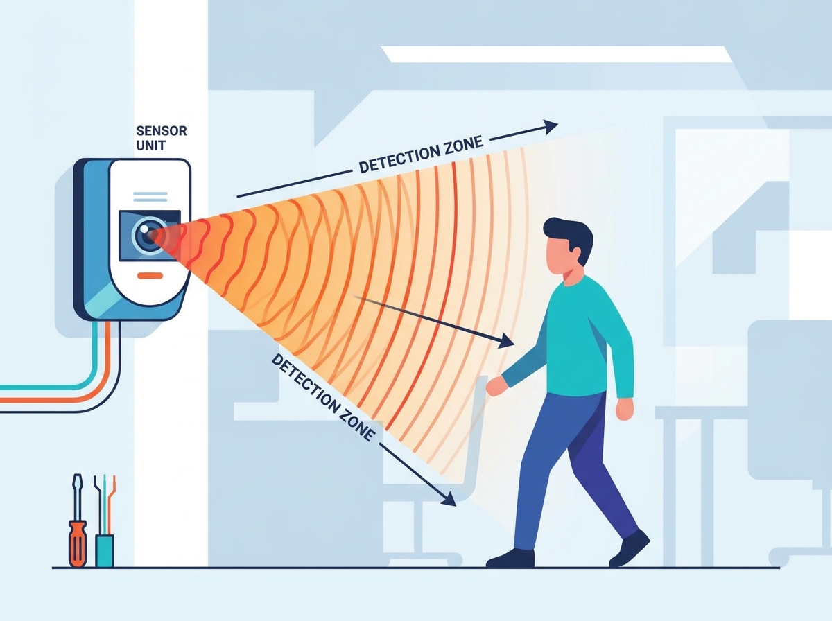
The concept of "cross-catch" detection dictates how you orient the device. Infrared motion sensors are most effective when an intruder walks across their lateral fields of view rather than walking directly toward them. When a person walks parallel to the sensor face, they cut across multiple detection zones rapidly. This rapid change in thermal energy across the pyroelectric element triggers the alarm relay instantly. If a person walks directly at the sensor, they remain in a single detection zone longer, which delays the trigger and creates a vulnerability in the security perimeter.
| Technology Type | Detection Method | Primary Application | Vulnerabilities |
Passive Infrared (PIR) | Detects ambient body heat changes across a grid | Interior rooms, hallways, standard security | HVAC drafts, direct sunlight, large pets |
Active Infrared (AIR) | Breaks a continuous point-to-point invisible beam | Perimeter fences, gate access, long corridors | Heavy fog, physical obstructions, misalignment |
Dual-Tech (PIR + Microwave) | Requires both heat and microwave doppler shift to trigger | Harsh environments, garages, warehouses | Microwave bleed-through walls, moving fan blades |
When planning the layout, you must map the expected path of an intruder. Identify the doors, windows, and hallways. Position the sensor so the expected path of travel intersects the detection grid at a 90-degree angle. This simple geometric adjustment drastically improves catch performance and reduces the need to crank up the sensor's sensitivity, which often leads to false alarms.
Analyze the geometry of the sensor lenses before drilling any holes. Mounting below 6 feet creates floor-level dead zones, allowing individuals to crawl under the detection grid. Mounting above 8 feet degrades detection directly beneath the sensor, creating a massive blind spot right at the wall base. You must address specific manufacturer guidelines requiring a precise 7.5 to 8 feet mounting height for optimized coverage. This height ensures the fresnel lens projects the optical fingers exactly as engineered.
Corner mounting is ideal for standard rooms. It maximizes the diagonal reach of the infrared sensor and leverages the physical structure of the room to track entry points. A standard 90-degree PIR lens fits perfectly into a corner, covering the entire volume of a square or rectangular room. Flat wall mounting is best for narrow corridors or entryways using long-range or curtain lenses. Ceiling mounting requires a specialized 360-degree PIR sensor. You should evaluate ceiling use cases for open-plan commercial spaces with partitioned cubicles where wall-mounted units would be blocked by furniture.
When retrofitting and replacing legacy sensors, follow a strict protocol to avoid damaging the existing alarm circuit:
Safely disconnect the control panel battery and AC transformer to kill power to the zone.
Remove the old sensor housing and label the legacy low-voltage wiring (Power +, Power -, Zone, Zone/COM).
Patch outdated mounting holes with spackle if the new sensor footprint does not cover them.
Evaluate if the existing structural location meets modern detection and tamper compliance standards. If the old sensor was mounted at 5 feet, you must pull the wire higher up the wall to meet the 7.5-foot standard.
Keep sensors away from AC units, heating vents, and fireplaces. Thermal drafts mimic the heat signature of a human body. Avoid pointing sensors at mirrors or glass doors that can reflect sudden changes in infrared energy. Sunlight hitting a mirror and bouncing into the PIR lens will cause a false alarm. Understand pet immunity weight and height thresholds. If a sensor is rated for a 40 lb pet, it assumes the pet remains on the floor. If a cat climbs onto a bookshelf within the sensor's field of view, the proximity to the lens makes the cat appear much larger thermally, triggering the alarm. Proper mounting height and physical alignment are mandatory for pet immunity to function.
Wireless systems offer rapid deployment, smart home compatibility, no drywall damage, and easy relocation. You can mount a wireless sensor in minutes using heavy-duty double-sided tape or a few drywall screws. However, they require strict battery replacement cycles. You also face potential RF signal interference from thick concrete walls, metal ductwork, and distance limitations from the central hub. Wireless sensors often use sleep timers to conserve battery; after detecting motion, they may power down their transmitter for 2 to 3 minutes. This is fine for residential setups but unacceptable for high-security tracking.
Hardwired systems provide continuous power, absolute immunity to wireless jamming, and lower long-term maintenance. You never have to roll a truck to change a battery. They involve complex cable routing through attics, basements, and wall cavities. You must calculate voltage drop over long wire runs. A standard 22/4 security cable can carry 12V DC power for hundreds of feet, but if you daisy-chain multiple sensors, the voltage at the end of the line might drop below the sensor's operating threshold (usually around 9.5V DC).
Evaluate UL-listed requirements for your specific site. Commercial deployments often dictate the choice between wireless mesh networks and hardwired zones. High-security environments like banks or jewelry stores mandate hardwired sensors with End-of-Line (EOL) resistor supervision to detect wire cutting or shorting attempts.
Locate wall studs using a magnetic stud finder. If a stud is unavailable at the optimal corner location, use heavy-duty drywall anchors rated for at least 10 lbs. The rear tamper plate must be mounted directly to a stud or solid wood. This ensures the system triggers an immediate alarm if the device is forcibly ripped from the wall. Many modern sensors feature a breakaway plastic tab on the backplate. You drive a screw through this tab into the stud. If an intruder smashes the sensor off the wall, the tab stays screwed to the stud, releasing the internal tamper switch and sending a 24-hour tamper alarm to the panel.
Route the 4-wire security cable through the wall knockout on the backplate. Strip the outer jacket back about two inches, being careful not to nick the inner conductors. Strip the individual wires about a quarter of an inch.
Connect the red wire to the 12V DC positive (+) terminal.
Connect the black wire to the 12V DC negative (-) terminal.
Wire the alarm relay (normally closed/NC) using the green and yellow wires.
Install End-of-Line (EOL) resistors directly at the sensor terminals, not at the control panel. Placing the resistor at the panel defeats the purpose of line supervision. Wire the resistor in series with the normally closed alarm relay.
Insert the lithium batteries, ensuring correct polarity. Enter pairing or programming mode on the central control panel. Execute the physical enrollment action required by the manufacturer. This usually involves pulling the battery tab, pressing down on the internal enrollment switch, or actuating the tamper switch to broadcast the unique RF serial number. Register the device and assign the correct zone type. Use "Interior Follower" for living rooms and hallways so the sensor ignores motion during the entry delay period if the front door is opened first. Use "Perimeter" for instant alarms in restricted areas.
Adjust the internal pins or DIP switches on the printed circuit board (PCB) to dictate how many infrared beams must be broken before triggering an alarm. A 1-pulse setting offers maximum sensitivity for high-security environments but increases false alarm risk. A 2-pulse or 3-pulse setting requires the target to cross multiple zones, filtering out brief thermal anomalies like a draft or a small rodent. Set the LED jumper to "ON" for the walk test, but consider turning it "OFF" for normal operation to hide the sensor's detection status from intruders.
Activate test mode on the control panel or directly on the device. Walk the perimeter and diagonal cross-sections of the room to map the exact detection boundaries. Watch the LED indicator; it should illuminate every time you cross a detection zone. Verify zero blind spots along the walls and directly under the sensor. Walk at different speeds—a slow creep and a fast walk—to ensure the pyroelectric element catches varying thermal changes.
Use physical lens masks to block out specific zones. Manufacturers often provide adhesive tape or plastic inserts that snap inside the lens cover. Mask off areas pointing toward staircases where a pet might climb high enough to trip the sensor. Adjust the vertical angle of the internal PCB if the sensor allows for physical tilt calibration. Sliding the PCB up or down alters the focal length of the lens, shifting the detection grid closer to or further from the wall.
Troubleshoot common post-install failures systematically. If the sensor stays "open" or "faulted" on the keypad, check your wiring polarities. Ensure you haven't shorted the zone wires together and verify the EOL resistor matches the panel's required ohm value (e.g., 2k, 4.7k, or 5.6k). For intermittent offline status on wireless units, troubleshoot the wireless range. Look for structural RF barriers like foil-backed insulation or large metal appliances blocking the signal path. Check the battery voltage with a multimeter under load. For delayed response times, lower the pulse count setting and physically realign the sensor to prioritize cross-catch paths rather than head-on approaches.
A reliable security deployment relies heavily on strategic placement and precise physical installation. You must respect the limitations of passive infrared technology and engineer your layout to maximize cross-catch opportunities while mitigating thermal drafts. Follow these next steps to finalize your deployment:
Seal the wire knockout hole behind the sensor with silicone or plumber's putty to prevent wall cavity drafts from blowing directly onto the pyroelectric element.
Establish a bi-annual maintenance schedule to clean the sensor lenses using a dry microfiber cloth to remove dust buildup that degrades infrared sensitivity.
Test battery voltages on all wireless units annually using a digital multimeter, replacing any cell that drops below 85% of its nominal voltage.
Conduct routine walk tests every six months to ensure new furniture, seasonal HVAC changes, or structural modifications haven't compromised the field of view.
A: The ideal mounting height for most infrared motion sensors is between 6 and 8 feet (1.8 to 2.4 meters) above the floor. For specific brands like 2GIG and Honeywell, aiming for 7.5 to 8 feet is highly recommended to maximize the sensor's range and ensure pet immunity features function correctly.
A: No, passive infrared (PIR) sensors cannot detect motion through glass. Glass acts as an insulator, blocking the thermal energy (body heat) that the sensor relies on to detect movement.
A: Avoid installing motion sensors directly facing windows, directly above or facing HVAC vents, near fireplaces, or pointing at reflective surfaces like large mirrors, as these cause rapid temperature changes and trigger false alarms.
A: Choose a wireless sensor for easy, drill-free installation and smart home integration. Choose a hardwired sensor for commercial security, permanent reliability, and environments where wireless signal interference is a concern.
A: A walk test is a diagnostic mode that allows you to physically walk through the sensor's coverage area. The sensor will flash an LED light when it detects your movement, helping you verify blind spots and confirm the detection range without triggering the actual alarm siren.
